
1. Introduction: Thermal Processing for High-Stress Engine Components
Modern internal combustion engines, heavy-duty diesel powertrains, and high-pressure industrial compressors place unprecedented operational demands on critical rotating assemblies. Specifically, the powertrain relies heavily on the structural integrity of the engine crankshaft and camshaft to convert reciprocating piston movement into continuous rotary power efficiently. Consequently, automotive engineers and plant managers constantly face a major mechanical dilemma: how to prevent catastrophic surface wear, galling, and dynamic fatigue failure in components subjected to millions of cyclic load revolutions. This critical engineering challenge is solved when manufacturing teams evaluate how induction hardening improves crankshaft and camshaft performance.
Traditional furnace heat treatments often heat the bulk volume of an entire steel component uniformly. However, this process frequently introduces severe dimensional warping, thermal distortion, and extreme energy inefficiency. Conversely, targeted electromagnetic thermal processing focuses energy exclusively where stress concentrations peak—at journal bearing surfaces, fillet radii, and cam lobe profiles. By transforming the outer layer into a wear-resistant martensitic microstructure while preserving a tough, ductile, shock-absorbing core, this advanced process creates the ideal mechanical balance. Furthermore, adopting advanced engineered solutions like custom induction coils ensures that localized heating is applied with surgical precision across complex shaft geometries.
In this deep-dive technical article, we will analyze the underlying electromagnetic physics, metallurgical grain structural transformations, fatigue resistance mechanisms, and operational efficiencies that explain how induction hardening improves crankshaft and camshaft performance over traditional batch furnace operations.
2. The Fundamentals: How Induction Hardening Works on Engine Shafts
To fully comprehend how induction hardening improves crankshaft and camshaft performance, one must first explore the foundational electromagnetic physics governing localized heat application. Unlike conventional convective or radiative gas furnaces, induction processing relies on localized electrical currents induced directly within the conductive metallic substrate itself.
The core operation begins when a high-frequency alternating current (AC) flows through an engineered copper coil situated near the target component zone. This AC current generates a localized, rapidly oscillating magnetic field. When the ferromagnetic steel crankshaft journal or camshaft lobe passes through or rotates within this magnetic field, high-density internal electric currents—known as eddy currents—are created beneath the metal surface. These eddy currents face natural electrical resistance in the steel lattice, producing instantaneous Joule heating (P=I2R).
3. Crankshaft Hardening: Eliminating Journal Wear & Fillet Fatigue
Crankshafts endure extreme operational strains, including cyclic bending moments and continuous torsional shear stresses during engine operation. The main journal bearings, connecting rod journals, and transition fillet radii bear the brunt of these dynamic forces. Understanding how induction hardening improves crankshaft and camshaft performance requires analyzing its impact on these critical zones.
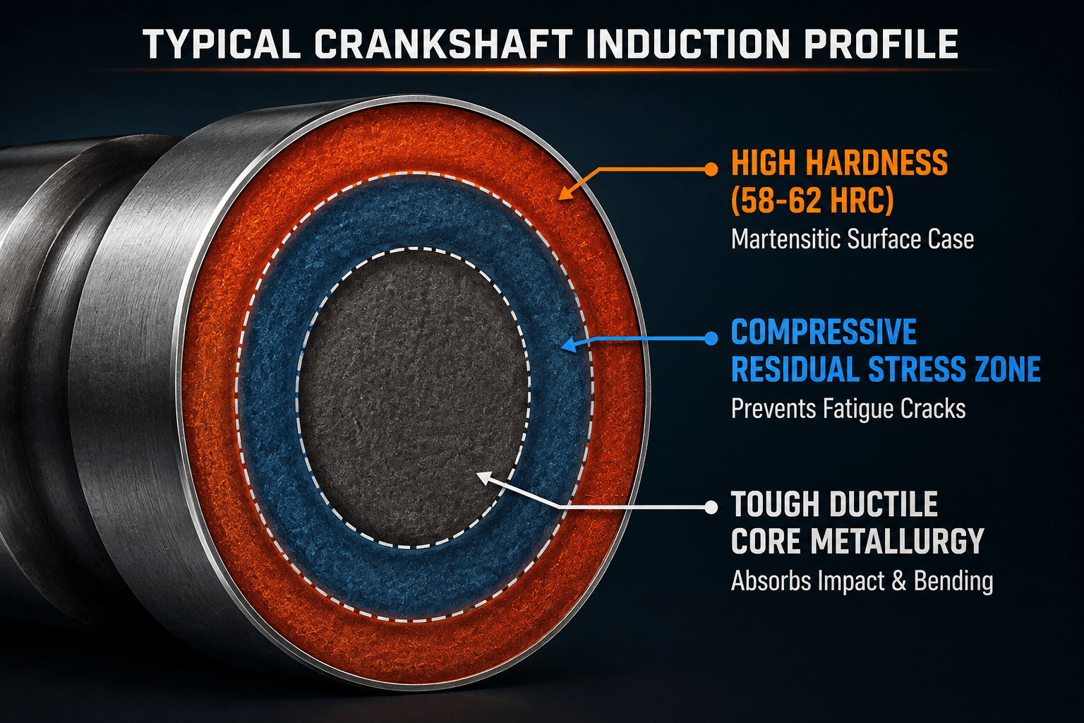
Enhancing Crankshaft Journal Wear Resistance
Journal surfaces experience continuous sliding friction against bearings, frequently subjected to abrasive particles suspended in engine oil. Utilizing a specialized surface hardening process raises journal surface hardness to 58–62 HRC (Rockwell Hardness Scale). This hardness barrier prevents surface scoring, micro-galling, and metal-to-metal adhesion, extending crankshaft operational lifespan even under high-torque, low-lubrication startup conditions.
Fillet Radii Hardening for Superior Fatigue Strength
Historically, the curved transition zones between crankshaft web faces and bearing journals—known as fillet radii—were primary sites for fatigue cracking. Standard thermal processes struggle to harden fillet contours evenly without causing distortion. However, implementing specialized crankshaft journal hardening techniques allows precision heating along the exact fillet geometry. This process induces beneficial residual compressive stress (often exceeding -600 MPa) along the outer surface. These compressive forces counteract external tensile operating loads, delivering substantial fatigue life enhancement and preventing crack initiation over hundreds of millions of rotation cycles.
4. Camshaft Hardening: Maximizing Lobe Surface Durability
Camshafts face distinct mechanical challenges compared to crankshafts. While crankshafts sustain fluid rotating motion, camshaft lobes endure severe localized Hertzian contact pressures from lifters or roller rocker arms. Therefore, examining how induction hardening improves crankshaft and camshaft performance requires exploring lobe profile requirements.
Combating Camshaft Lobe Wear and Pitting
As the tip of a cam lobe actuates an engine valve against stiff spring pressure, contact stresses can easily exceed 1,000 MPa. Without targeted surface modification, lobes suffer rapid scuffing, spalling, and surface pitting. Achieving optimum camshaft lobe wear resistance requires a precise, uniform martensitic depth along the lobe apex, flank, and base circle. Induction systems deliver concentrated energy to these critical contact points, generating deep wear-resistant layers while keeping shaft centers soft to facilitate secondary straightening if required.
Controlling Distortion Along Multi-Lobe Camshafts
Because camshafts are relatively long, thin shafts with multiple protruding lobes, traditional furnace heating causes significant thermal bowing and twisting. By executing precise scan hardening or single-shot induction cycles, total heat input is reduced by over 70% compared to atmospheric batch furnaces. Consequently, this leads to exceptional distortion minimization, drastically reducing or eliminating expensive post-heat-treatment cylindrical grinding operations. Manufacturing teams often pair these machines with advanced induction power supplies to maintain exact frequency and power control across all lobes.
5. Technical Comparative Matrix: Process Performance Analysis
To highlight why global automotive and industrial equipment manufacturers prefer localized electromagnetic processing over legacy methods, the table below compares key engineering parameters:
| Engineering Parameter | Induction Hardening Process | Gas Carburizing / Furnace | Through-Hardening Methods |
| Heat Application Zone | Localized (Journals, Fillets, Lobes) | Entire Surface Area | Entire Component Volume |
| Thermal Cycle Duration | 3 to 15 Seconds per zone | 6 to 20 Hours (Diffusion time) | 1 to 4 Hours |
| Case Depth Control | 0.5 mm to 10+ mm (Frequency controlled) | 0.2 mm to 2.5 mm (Time/Carbon limit) | Uniform throughout cross-section |
| Surface Hardness Achieved | 58 – 64 HRC | 56 – 62 HRC | 50 – 55 HRC (Core brittle) |
| Component Distortion | Extremely Low (Minimal post-grind) | Moderate to High | High (Requires heavy post-grind) |
| Inline Automation | 100% Integrated into CNC Lines | Off-site / Batch Yard required | Batch processing only |
| Energy Efficiency | High (Heats targeted zone only) | Low (Heats entire furnace) | Low efficiency |
For an authoritative deeper look into material transformation standards and heat treating parameters, refer to the technical industry guidance provided by ASM International Materials Information Society and technical design resources from SAE International.
6. Key Metallurgical Benefits: Compressive Stresses & Microstructure
The fundamental reason why modern powertrain designers specify induction technology lies in microstructural management. When analyzing how induction hardening improves crankshaft and camshaft performance, three primary metallurgical mechanisms stand out:
- High Compressive Residual Stresses: During rapid liquid quenching, the outer heated layer converts to high-density martensite, expanding in volume. However, the cool interior core resists this expansion, pulling the surface inward. This generates powerful surface compressive stresses that actively inhibit fatigue crack formation under high bending and torsional strain.
- Grain Refinement: Because induction heating operates rapidly (often taking only seconds to reach austenitizing temperature), grain growth is suppressed. This results in ultra-fine martensite crystals that provide exceptional fracture toughness alongside high hardness values.
- Tailored Transition Zones: Fine-tuning power supply frequency produces a smooth, gradual transition from the hardened case layer to the core steel structure. This smooth gradient prevents surface shelling or delamination under intense contact forces.
7. Operational Efficiency, Energy Savings & Industry 4.0 Integration
Beyond metallurgical advantages, adopting electromagnetic surface treatments delivers compelling financial and operational benefits. Traditional atmospheric furnaces must run continuously, consuming gas and electricity even during operational downtime. In contrast, induction systems consume power only during active heating cycles, reducing factory energy usage by up to 60%.
Furthermore, modern induction systems fit directly into lean manufacturing cells alongside automated CNC turning and grinding equipment. Using single-piece flow setups, robotic arms transfer turned crankshafts directly into automated vertical induction scanners. The part is hardened, quenched, tempered, and verified in seconds—eliminating work-in-progress (WIP) storage and reducing production lead times from days to minutes. Facilities looking to modernize can explore specialized automotive induction hardening solutions to optimize plant throughput.
Pitch & Call to Action (CTA)
Upgrade Your Heat Treatment Precision with Induction India
Are you experiencing component fatigue failure, excessive post-heat-treatment distortion, or long production bottlenecks in your automotive or industrial manufacturing facility?
Induction India provides custom-engineered, state-of-the-art induction hardening machines, high-efficiency power supplies, and custom-tailored induction coils for automotive components engineered specifically for heavy-duty crankshafts, camshafts, and precision gears. Our team of expert metallurgical and electrical engineers can design custom turnkey solutions tailored to your specific material grades, case depth requirements, and production throughput targets.
Ready to transform your thermal processing efficiency?
Contact Induction India Today for a Custom Engineering Consultation
8. Frequently Asked Questions (Q&A)
Q1: How does induction hardening improve crankshaft and camshaft performance compared to traditional gas carburizing?
Induction hardening delivers targeted heat directly to critical wear areas like journals, fillets, and cam lobes without heating the entire component. This preserves a tough, flexible core while creating higher surface compressive stresses and ultra-hard surface layers, significantly boosting fatigue resistance while minimizing thermal distortion.
Q2: What carbon content is required in steel for direct induction hardening?
Steels with medium-to-high carbon content (typically 0.35% to 0.65% carbon, such as AISI 1045, 4140, 4340, or 5150) are ideal for direct induction hardening. They contain sufficient carbon to achieve 58–62 HRC hardness upon quenching without requiring multi-hour carbon diffusion cycles.
Q3: Can induction hardening prevent fatigue cracks in crankshaft fillet radii?
Yes. By using custom-contoured inductor coils, heat can be concentrated directly along the curved fillet radii between the journals and web faces. Quenching generates strong residual compressive stresses in these high-stress zones, effectively blocking fatigue crack initiation.
Q4: How is case depth controlled during induction hardening of camshafts?
Case depth is primarily controlled by adjusting the operating frequency of the induction power supply and the heating cycle duration. Higher frequencies (e.g., 100 kHz – 300 kHz) produce shallow case depths suitable for camshaft lobes, while lower frequencies (e.g., 1 kHz – 10 kHz) penetrate deeper into heavy crankshaft journals.
Q5: Is post-heat-treatment grinding required after induction hardening?
Because induction heating is localized and extremely fast, overall thermal distortion is drastically reduced compared to furnace treatments. While light finish grinding is often performed to meet ultra-precise micro-inch tolerances, heavy rough-grinding pass cycles are eliminated.