
Industrial gearboxes operate under relentless mechanical loads, experiencing continuous cyclic stress, contact pressures, and thermal friction. In heavy duty applications across automotive power transmission, wind energy turbines, mining machinery, and aerospace systems, gear failure is simply not an option. When designing high performance power transmission components, metallurgists and mechanical engineers must select an optimal thermal treatment method. A fundamental decision continually surfaces during the engineering design phase: Induction Hardening vs. Carburizing for Industrial Gears: Which Yields Better Fatigue Life?
Both electromagnetic induction hardening and atmospheric case carburizing increase the surface hardness of steel gear teeth while preserving a tough interior core. However, the underlying thermal mechanics, residual stress patterns, geometric distortion levels, and microscopic fatigue resistance mechanisms differ significantly.
In this comprehensive technical guide, we evaluate Induction Hardening vs. Carburizing for Industrial Gears: Which Yields Better Fatigue Life, analyzing bending fatigue, contact fatigue, microstructural transformations, production throughput, and cost effectiveness.
Technical Overview: Surface Hardening Methods for Industrial Gears
To evaluate how thermal processing choices influence gear fatigue life, we must first examine how both methodologies modify the material structure of a gear profile.
Understanding Induction Hardening
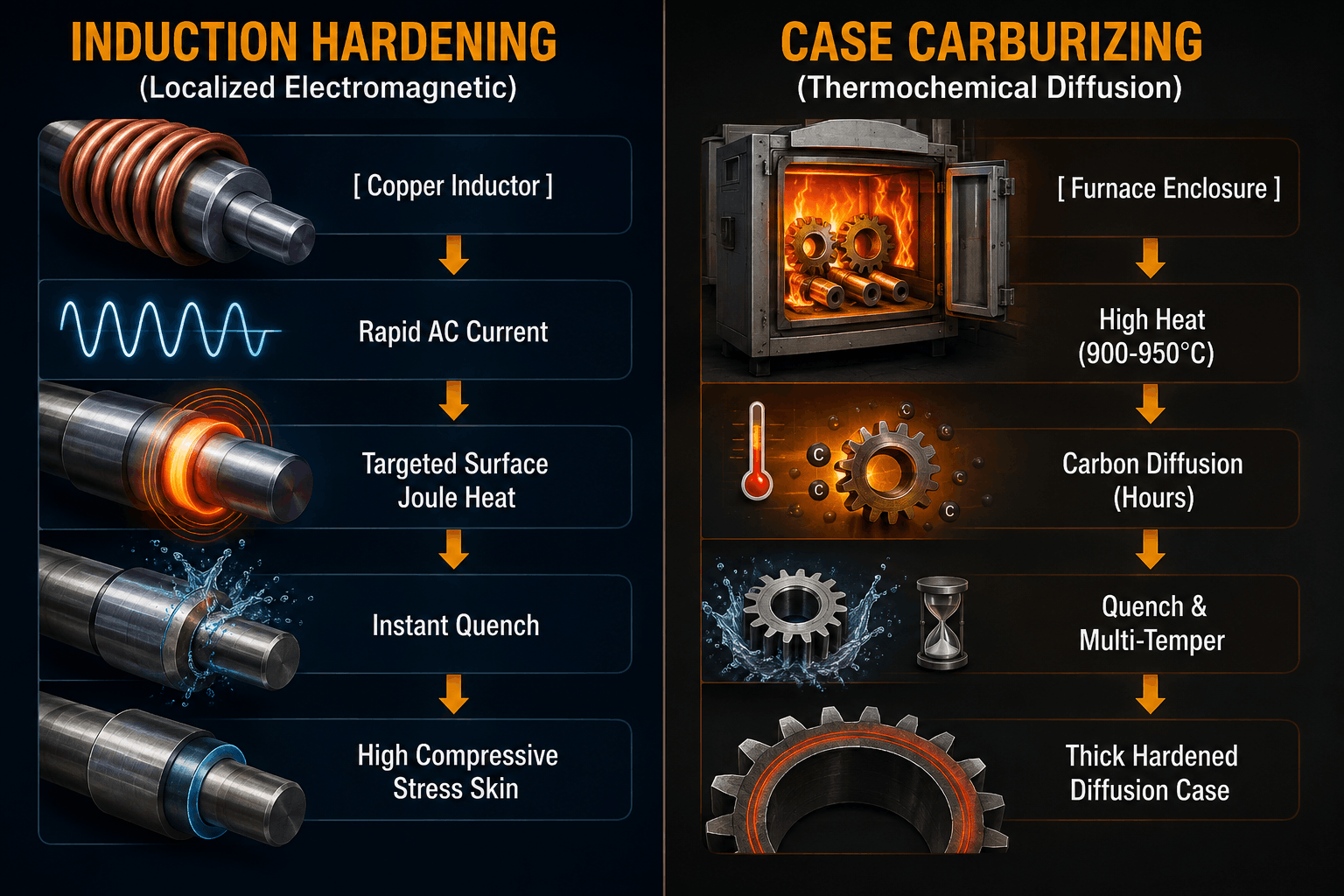
Induction surface processing uses high frequency alternating electrical current passed through a custom copper inductor coil to generate localized heating. When an electrically conductive steel gear is placed inside this rapidly oscillating electromagnetic field, intense eddy currents are induced within the surface layer of the metal.
Resistance to these induced eddy currents generates rapid surface heat through the Joule effect. This raises the outer temperature of the gear teeth above the critical transformation range (typically between 850°C and 1050°C) in a matter of seconds. The component is then immediately quenched using an integrated liquid spray ring, transforming the outer austenitic skin into a wear resistant martensitic microstructure.
Because energy is transferred contactlessly into the targeted surface zone, the core of the gear remains unheated, preserving its original toughness and ductile properties. Manufacturers routinely deploy state-of-the-art induction hardening machines directly within automated machining lines to achieve high process repeatability and low cycle times.
Understanding Case Carburizing
Carburizing is a classic thermochemical surface diffusion treatment performed inside a sealed batch furnace or continuous atmospheric furnace. Low carbon steel gears are heated to elevated temperatures (usually between 900°C and 950°C) within a carbon rich gaseous atmosphere for several hours.
During this long thermal soaking phase, carbon atoms slowly migrate into the austenitic surface layer of the gear material. After achieving the desired carbon gradient, the entire component is quenched in an oil or polymer bath to transform the high carbon outer layer into martensite while leaving the low carbon core softer.
While carburizing produces a deep, uniform carbon enriched case across complex geometric surfaces, heating an entire gear to high temperatures for extended periods introduces significant thermal distortion and requires high energy consumption.
Structural Stress Mechanisms in Gear Teeth
Industrial gears fail primarily due to two distinct mechanical mechanisms: bending fatigue at the tooth root fillet and contact fatigue (pitting or spalling) on the tooth flank surface.
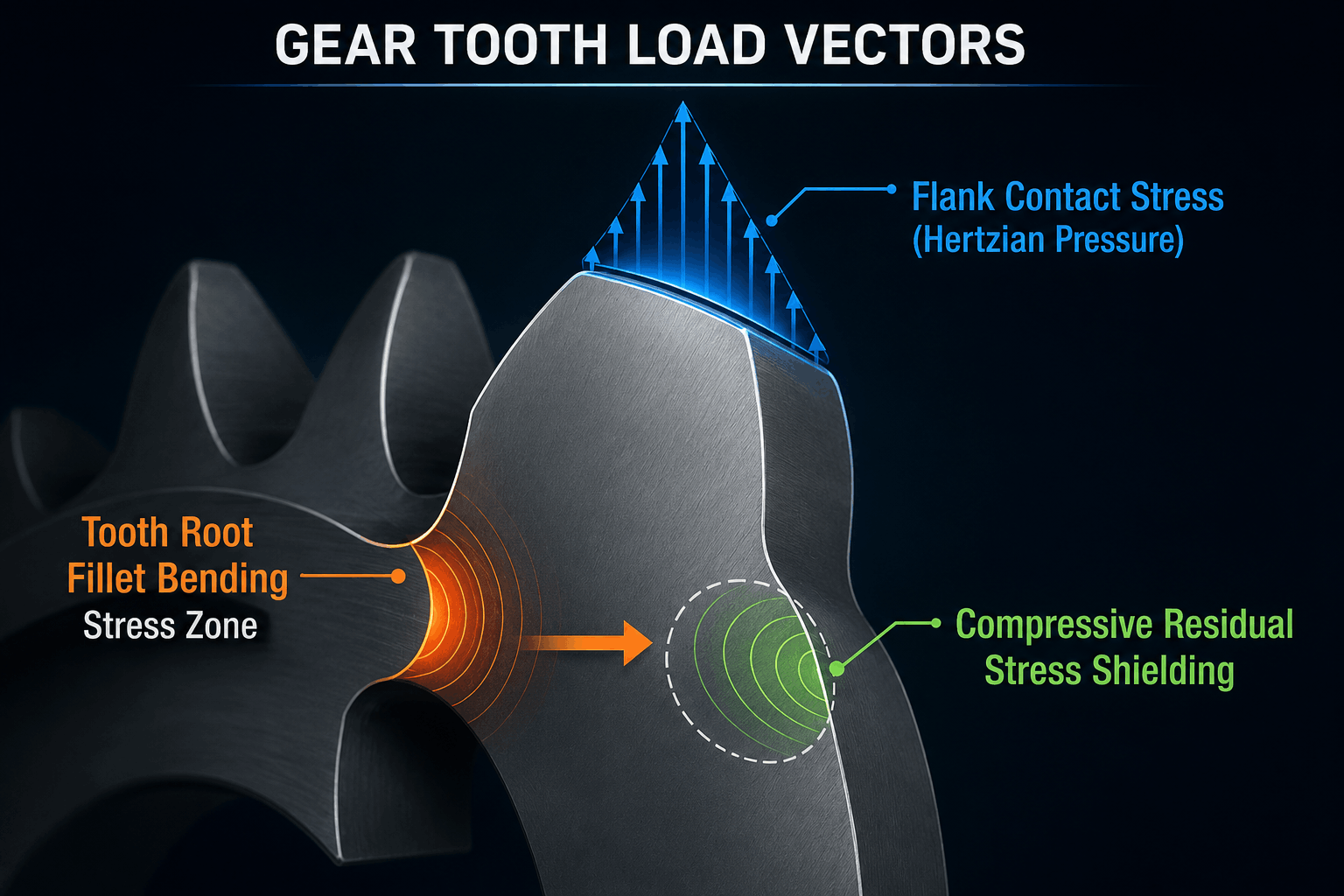
- Root Bending Fatigue: Occurs when cyclic bending forces create maximum tensile stress at the tooth root fillet. Over millions of cycles, microscopic cracks initiate at the surface and propagate through the tooth base, leading to catastrophic tooth breakage.
- Flank Contact Fatigue (Hertzian Stress): Occurs under high contact pressure between mating gear teeth. Subsurface shear stress causes microscopic pitting, spalling, and surface degradation along the active pitch line.
To maximize gear service life, the surface hardening treatment must introduce high compressive residual stress on the exterior surface while retaining core ductility.
Direct Comparison: Induction Hardening vs. Carburizing for Industrial Gears
To evaluate how these treatments affect gear operational lifespan, the following comparative matrix highlights critical engineering parameters:
| Performance Metric | Induction Hardening Process | Case Carburizing Method |
| Primary Stress Mode | Superior surface compressive residual stress | Moderate compressive stress with deep carbon diffusion |
| Tooth Root Fatigue Resistance | Outstanding (contour induction scanning) | Very High (uniform case along entire fillet) |
| Contact Fatigue (Pitting) | Excellent; customizable hardness profiles | Excellent; consistent high surface carbon |
| Thermal Distortion | Minimal; localized skin heating | Moderate to High; uniform thermal expansion |
| Thermal Processing Cycle Time | Seconds to minutes per component | 8 to 24+ hours per batch |
| Energy Consumption | Direct electrical efficiency (Instant ON/OFF) | Continuous gas/electric furnace heating |
| In-Line Automation Integration | Seamless integration with CNC production lines | Requires dedicated furnace bays or offsite transport |
| Material Requirements | Medium-carbon steels (AISI 1045, 4140, 4340) | Low-carbon carburizing steels (AISI 1018, 8620) |
Evaluating Fatigue Life: Which Method Wins?
When asking Induction Hardening vs. Carburizing for Industrial Gears: Which Yields Better Fatigue Life, the answer depends on the dominant fatigue mode and the specific geometry of the gear teeth.
Tooth Root Bending Fatigue Life
In heavy duty industrial gearboxes subject to high shock loads, tooth root bending fatigue is the primary failure mode. Contour induction hardening—where specialized inductors accurately trace the tooth profile down into the root fillet—generates exceptionally high compressive residual stress at the surface.
Because induction heating only transforms a thin outer skin while the bulk core remains cool and rigid, the volumetric expansion during rapid martensitic transformation creates surface compressive stresses ranging from -600 MPa to -1000 MPa. This intense compression directly counteracts incoming operational tensile bending forces, arresting crack initiation at the tooth root fillet and dramatically extending fatigue life.
Carburizing also generates compressive residual surface stresses. However, because the entire gear is heated uniformly, thermal gradients during oil quenching can lower the net compressive stress at the root fillet compared to specialized induction contour hardening.
For a deeper dive into materials science standards, researchers at the ASM International Materials Information Center highlight that compressive stress distribution is a critical driver for high-cycle fatigue survival.
Surface Contact Fatigue & Pitting Resistance
Contact fatigue resistance relies on surface hardness, case depth, and microstructural homogeneity along the gear flank.
Carburizing excels at providing a deep, continuous, high-carbon martensitic layer with high surface hardness (typically 58 to 62 HRC) across complex or small-pitch gear teeth. The gradual carbon gradient created by thermal diffusion ensures smooth transition zones, offering resistance to subsurface shear stress under rolling-sliding contact.
Induction hardening achieves equivalent or higher surface hardness values (up to 62+ HRC) on medium-carbon alloy steels. When executed using dual-frequency power supplies, induction hardening produces precise contour-hardened profiles that match or exceed the rolling contact fatigue resistance of carburized gears.
Technical Case Study: Gear Distortion & Manufacturing Impact
Beyond raw fatigue limits, dimensional stability after heat treatment directly affects gear meshing precision, noise levels, and operational longevity.
During conventional carburizing, components endure prolonged exposure to high temperatures inside a gas furnace followed by full immersion quenching. This uniform volumetric heating causes dimensional warping and twisting along gear teeth. To restore precise involute profiles, manufacturers must perform extensive post-heat-treatment grinding. Intensive grinding operations increase production costs, consume valuable floor space, and risk removing parts of the hardened case layer.
In contrast, localized processing using optimized custom induction coils restricts heat precisely to the tooth skin. The unheated interior structural core acts as a rigid support frame that minimizes thermal deformation. Consequently, gears treated via induction hardening maintain tighter tolerances post-quench, significantly reducing or eliminating expensive secondary grinding operations.
According to manufacturing efficiency studies from the American Gear Manufacturers Association (AGMA), controlling post-treatment distortion is key to preventing gear pitch errors and uneven load distribution that degrade operational fatigue life.
Material Selection: Matching Steel Alloys to the Hardening Method
Selecting the correct steel grade is critical when deciding between induction hardening and carburizing.
Steels for Induction Hardening
Induction heating relies on carbon already present within the base alloy to form martensite during quenching. Medium-carbon steels and medium-carbon alloy steels perform exceptionally well:
- AISI 1045 / 1050: Standard carbon steels ideal for medium duty spur and helical gears.
- AISI 4140 / 42CrMo4: Chromium-molybdenum alloy offering superior core strength and fatigue toughness.
- AISI 4340 / EN24: Nickel-chromium-moly alloy engineered for heavy duty aerospace and industrial drive components.
By pairing medium-carbon alloy steels with dynamic power supplies, process engineers can achieve tailored core toughness alongside high surface compressive stresses.
Steels for Case Carburizing
Carburizing uses low-carbon steels that absorb carbon during extended thermal cycles:
- AISI 1018 / 1020: Low-carbon mild steels suitable for light to medium duty gears.
- AISI 8620 / 20NiCrMo2: Popular nickel-chromium-moly carburizing steel delivering good core strength.
- AISI 9310: Premium aircraft grade carburizing alloy offering high core toughness.
Operational Efficiency, Industry 4.0, and Sustainability
In modern industrial facilities, heat treatment processes are evaluated not only on metallurgical performance, but also on energy usage, production footprint, and automation compatibility.
- Energy Efficiency: Gas carburizing furnaces require continuous heating cycles to maintain operating temperatures, leading to standby thermal losses. Induction systems use direct electrical transfer, drawing power only during active heating cycles and reducing energy consumption per workpiece.
- Inline Manufacturing: Compact induction hardening systems can be installed directly within automated machining cells adjacent to CNC gear shapers and hobbing machines. This setup eliminates work-in-progress (WIP) storage queues and off-site transportation costs.
- Industry 4.0 Data Integration: Advanced induction power units feature continuous monitoring of frequency, voltage, power, and quench flow rates. Integrating these data metrics into Industry 4.0 smart factory networks ensures 100% traceably compliant quality control for critical gear batches.
Making the Engineering Decision: Selection Matrix
When deciding between Induction Hardening vs. Carburizing for Industrial Gears: Which Yields Better Fatigue Life, consider these key guidelines:
Choose Induction Hardening when:
- Maximizing tooth root bending fatigue life via high compressive surface stresses is critical.
- Tighter dimensional stability is required to minimize post-treatment grinding costs.
- You want to integrate thermal processing directly into automated, in-line CNC production workflows.
- Reducing carbon emissions and energy consumption per gear aligns with facility goals.
- You are using medium-carbon alloy steels (e.g., AISI 4140, 4340, 1045).
- Choose Carburizing when:
- Processing small-pitch gear teeth (under 2–3 module) where induction coil clearance is limited.
- Treating complex internal ring gears with narrow recesses that make localized heating difficult.
- Working with low-carbon steel alloys that require external carbon enrichment.
- Operating traditional batch processing workflows where extended thermal cycles fit existing schedules.
Partner with Induction Equipment India for Precision Thermal Processing
Optimizing gear manufacturing requires thermal equipment tailored to your exact production tolerances and material grades.
As part of SAET SpA Italy and the global Ajax Tocco Magnethermic Corporation group, Induction Equipment (India) Pvt. Ltd. brings over 60 years of global engineering experience and more than 4,000 installations worldwide to industrial manufacturing. Operating from our advanced facility in Pune, India, we design, build, and deploy custom thermal processing systems across automotive, heavy engineering, wind energy, and aerospace sectors.
Our comprehensive engineering capabilities include:
- Custom Machine Manufacturing: Single-station, multi-spindle, and robotic vertical scan induction hardening machines.
- Inductor Design & 3D Printed Coils: Custom copper coil designs engineered for precise gear contour scanning.
- Process Simulation & R&D Testing: In-house metallurgical laboratories for depth validation and stress profiling.
- Turnkey Support: Complete aftermarket servicing, spare parts, machine overhauls, and Industry 4.0 integration.
Contact our metallurgical application specialists today to schedule a process evaluation, optimize your gear fatigue life, or request a custom machinery quote.
Frequently Asked Questions (Q&A)
Q1: Does induction hardening provide better root bending fatigue life than carburizing for industrial gears?
Yes, when using tailored tooth-by-tooth or contour scanning methods, induction hardening can generate higher compressive residual stress levels (-600 to -1000 MPa) at the tooth root fillet than carburizing. This compressive surface layer directly counteracts tensile fatigue loads, arresting micro-crack initiation and extending root bending fatigue life.
Q2: What steel grades are best suited for induction hardening of industrial gears?
Medium-carbon steels and medium-carbon alloy steels containing between 0.35% and 0.65% carbon are best suited for induction processing. Popular grades include AISI 1045, AISI 4140 (42CrMo4), AISI 4340, and EN24. These alloys contain sufficient carbon to transform directly into a martensitic surface layer without extra chemical enrichment.
Q3: How does induction hardening reduce post-treatment grinding costs compared to carburizing?
Carburizing heats the entire gear uniformly inside a furnace, which can lead to structural distortion and warping during quenching. Induction hardening restricts heat exclusively to the outer tooth skin while the core remains cool. This localized heating minimizes distortion, keeping the gear within tight tolerances and reducing or eliminating post-heat-treatment grinding passes.
Q4: Can small-pitch, high-density gears be induction hardened effectively?
Yes. While small-pitch gears (under 2 module) historically presented coil clearance challenges, modern multi-frequency power supplies and 3D printed custom induction coils make it possible to perform contour induction hardening on fine-pitch gear profiles.
Q5: How do energy requirements compare between induction hardening and atmospheric furnace carburizing?
Induction hardening is significantly more energy efficient. It uses direct electromagnetic energy transfer that draws power only during active heating cycles (seconds to minutes per part). Gas carburizing furnaces must run continuously for 8 to 24+ hours per batch, resulting in higher overall energy consumption and carbon emissions.